Verilog Introduction
Verilog is a language using which a designer can specify the behavior, or the functionality, or the structure of some given hardware; some specified hardware circuit. this language is also called Hardware Description Languages (HDL).
HDL’s allows the design to be simulated earlier in the design cycle in order to correct errors or experiment with different architectures. Designs described in HDL are technology-independent, easy to design and debug, and are usually more readable than schematics, particularly for large circuits.
Verilog can be used at several levels-
1) High level Behavioral
- Behavioral models in Verilog contain procedural statements, which control the simulation and manipulate variables of the data types, these all statements are contained within the procedures. Each of the procedure has an activity flow associated with it.
- Below is a Half Adder example-
//below is code for half adder
module half_adder(a,b,sum,cout);
input a,b;
output sum,cout; // sum and carry
assign sum = a^b;
assign cout = a&b ;
endmodule
2) Register transfer level
- Designs using the Register-Transfer Level specify a circuit’s characteristics using operations and the transfer of data between the registers
3) Gate level
- Designing circuits using basic logic gates is known as gate-level modeling.
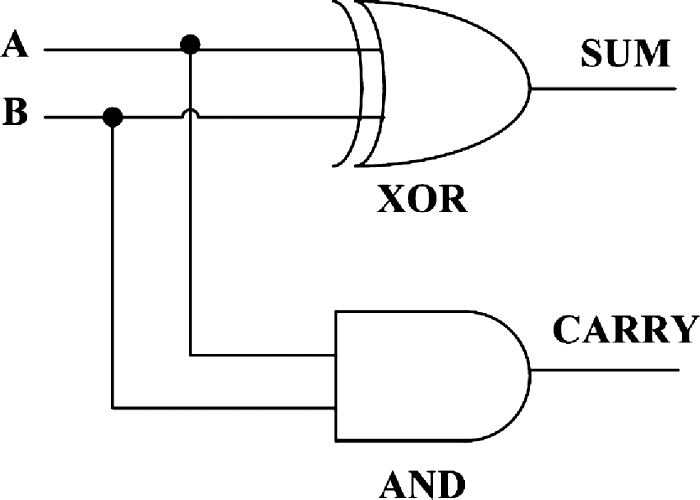
It is a low-level abstraction that describes design in terms of gates. - Below is simple gate level design of a Half Adder
// code your half adder design
module half_add(a,b,s,c);
input a,b;
output s,c;
// gate level design of half adder
xor x1(s,a,b);
and a1(c,a,b);
endmodule :half_add