Verilog Bitwise Operators

The bitwise operators shall perform bitwise manipulations on the operands; that is, the operator shall
combine a bit in one operand with its corresponding bit in the other operand to calculate 1 bit for the result.

Below are the results for each possible combinations

1 Bitwise binary AND operator:

2. Bitwise binary OR operator:

3. Bitwise binary exclusive or operator

<< Previous | Next >>

Verilog Logical Operators

The operators logical and (&&) and logical or (||) are logical connectives. The result of the evaluation of a logical comparison shall be 1 (defined as true), 0 (defined as false), or, if the result is ambiguous, the unknown value (x). The precedence of && is greater than that of ||, and both are lower than relational and equality operators. 

A third logical operator is the unary logical negation operator (!). The negation operator converts a nonzero or true operand into 0 and a zero or false operand into 1. An ambiguous truth value remains as x.

Example 1—If reg alpha holds the integer value 237 and beta holds the value zero, then the following
examples perform as described:
regA = alpha && beta; // regA is set to 0
regB = alpha || beta; // regB is set to 1

<< Previous | Next >>

Verilog Equality Operators

All four equality operators shall have the same precedence.

For the logical equality and logical inequality operators (== and !=), if, due to unknown or high-impedance bits in the operands, the relation is ambiguous, then the result shall be a 1-bit unknown value (x). 

For the case equality and case inequality operators (=== and !==), the comparison shall be done just as it is in the procedural case statement (see 9.5). Bits that are x or z shall be included in the comparison and shall match for the result to be considered equal. The result of these operators shall always be a known value, either 1 or 0.

<< Previous | Next >>

Verilog Rational Operators

Relational operators are used for comparing values. They return a Boolean result indicating the relationship between the operands.
Definitions of rational operator shown in below table-

An expression using these relational operators shall yield the scalar value 0 if the specified relation is false or the value 1 if it is true. If either operand of a relational operator contains an unknown (x) or highimpedance (z) value, then the result shall be a 1-bit unknown value (x).

When one or both operands of a relational expression are unsigned, the expression shall be interpreted as a comparison between unsigned values. If the operands are of unequal bit lengths, the smaller operand shall be zero-extended to the size of the larger operand. 

When both operands are signed, the expression shall be interpreted as a comparison between signed values. If the operands are of unequal bit lengths, the smaller operand shall be sign-extended to the size of the larger operand. 

If either operand is a real operand, then the other operand shall be converted to an equivalent real value and the expression shall be interpreted as a comparison between real values.

<< Previous | Next >>

Verilog Operators and Operands

We will understand the various Verilog operators and operands, their types, and their applications in digital circuit design.
Verilog operators are symbols that represent computations or operations on operands. They are classified into several categories based on their functionality.

Arithmetic operators:
Arithmetic operators perform mathematical operations on operands. Common arithmetic operators in Verilog such as addition, subtraction, multiplication, division, and modulus.

reg [3:0] result;
reg [3:0] a = 3;
reg [3:0] b = 5;
always @* begin
    result = a + b;   // Addition
    result = a - b;   // Subtraction
    result = a * b;   // Multiplication
    result = a / b;   // Division
    result = a % b;   // Modulus
end

<< Previous | Next >>

Verification

Que 21: What are features you will verify for a Register?
Ans 21:
We need to verify the following features in a Register verification:

  • Reset values of the register.
  • We can write and read back the same value.
  • We can write hAA,h55, h00 andhFF data to ensure no connected bits.
  • Write to the register and backdoor read from a register to ensure writing at the same address.
  • Other features are clear on read and clear on write.

Que 22: How a UVM driver is connected with a UVM sequencer?
Ans 22:
The UVM driver class contains a TLM port called uvm_seq_item_pull_port which is connected to a uvm_seq_item_pull_export of UVM sequencer in the connect phase of a UVM agent.


Que 23: What is an analysis port? What is the use of an analysis port? What are the different types of analysis ports?
Ans 23:
Analysis port (class uvm_tlm_analysis_port) — a specific type of transaction-level port that can be connected to zero, one, or many analysis exports and through which a component may call the method write implemented in another component, specifically a subscriber.
port, export, and imp classes used for transaction analysis.
uvm_analysis_port
Broadcasts a value to all subscribers implementing a uvm_analysis_imp.
uvm_analysis_imp
Receives all transactions broadcasted by a uvm_analysis_port.
uvm_analysis_export
Exports a lower-level uvm_analysis_imp to its parent.


Que 24: What are assertions? What are the different types of assertions?
Ans 24:
Assertions are used to check the behavior of a design, It is written in the form of properties that should be true throughout the simulation. Assert property is used to activate the property and cover property is used to check if the property is getting covered. There are two types of immediate assertions and concurrent assertions. Immediate Assertions: Immediate assertions are procedural statements and are mainly used in simulation. An assertion is basically a statement that something must be true, similar to the if statement. Concurrent Assertions: These validate the circuit behavior throughout the simulation, It gets evaluated based on the clock trigger.


Que 25: What is the use of the “dist” keyword in constraint? What is the difference between “:/” and “:=” symbols in constraints?
Ans 25:
The “dist” keyword is used for distribution in constraints. It is used when we need to assign different weights to the elements of random variables. eg.: A dist { 5 := 1; [10:12] := 2 ; [15:16] :/ 2 }
Two symbols used with dist keyword “:=” assign mention weightage to each element and “/=” assigns the mention weightage divided by the number of variables. In the above example, The weightage for each element will be 5 -> 1, 10 -> 2, 11 -> 2, 12 -> 2, 15 -> 2/2, 16 -> 2/2.


Que 26: What is UVM? What is the advantage of UVM?
Ans 26:
UVM is a methodology used for functional verification.

  • Reusability through test bench
  • Plug & Play of verification Ips
  • Generic Testbench Development
  • Sequence-based stimulus generation
  • Vendor & Simulator Independent
  • Smart Test bench i.e. generate legal stimulus from pre-planned coverage plan
  • Support CDV –Coverage-Driven Verification
  • Support CRV –Constraint Random Verification
  • Register modeling

Que 27: What is the difference between “uvm_component” and “uvm_object”?
Ans 27:
“uvm_component” is used to construct the UVM environment fixed part. They are used to make testbench components that do not change throughout the simulation. Classes are registered with the factory using macro uvm_component_utils. “uvm_object” is used for UVM transient objects like uvm_seq_item, uvm_transaction, and uvm_sequence. The base class uvm_object is also used for configuration objects, i.e. classes that contain configuration data to configure uvm_components, sequences, etc. Classes are registered with the factory using macrouvm_object_utils.


Que 28: What is uvm_phase? What are the different phases in UVM?
Ans 28:
UVM phases act as a synchronizing mechanism in the simulation because phases are defined as callbacks, classes derived from uvm_component can perform useful work in the callback phase method. Different phases in UVM are :

  • build_phase
  • connect_phase
  • end_of_elaboration_phase
  • start_of_simulation_phase
  • run_phase
  • extract_phase
  • check_phase
  • report_phase

Sub-phases in run_phase are :

  • reset_phase
  • configure_phase
  • main_phase
  • shutdown_phase

Que 29: Which UVM phase is top-down, bottom–up & parallel?
Ans 29:
The build phase is top-down and the Run phase is a parallel phase as all the run phases run parallelly. All other phases are bottom-up.


Que 30: Which phase is the task/time-consuming phase?
Ans 30:
The run phase is a task in UVM, while all other phases are functions, so the only Run phase is a time-consuming phase.

<< Previous | Next >>

Verification

Que 11: Write a code to generate a 100MHz clock.
Ans 11:
To generate a 100MHz clock, which is a 10ns time period. We can write the below code.

module clk_100M ;
reg clk ;
initial begin
clk = 0;
forever #5ns clk = !clk ;
end 
endmodule

Que 12: What is a clocking block, What are the uses of a clocking block?
Ans 12: A clocking block is a set of signals synchronized on a particular clock. It basically separates the time-related details from the structural, functional, and procedural elements of a test bench. It helps the designer develop test benches in terms of transactions and cycles.


Que 13: Write a code to generate a 10MHz clock with a 60% duty cycle.
Ans 13:
To generate a 10MHz clock, which is a 100ns time period. We can write the below code.

module clk_10M_60D ;
reg clk ;
initial begin
clk = 0 ;
forever begin
40ns clk = !clk ;
60ns clk = !clk ; end
end endmodule

Que 14: Write a code to generate two clocks of 10Mhz with 90o Phase shift.
Ans 14: To generate a 10MHz clock, which is a 100ns time period. To shift the 90o phase of the second clock we can delay the second clock by 100ns x 360o/ 90o.

module clk_10M_90d ;
reg clk1 , clk2 ;
initial begin
clk1 = 0 ;
forever
50ns clk1 = !clk1 ;
end
initial begin
clk2 = 0 ;
25ns ;
forever
50ns clk2 = !clk2 ;
end endmodule

Que 15: What are the steps in digital verification flow?
Ans 15:
The main steps involved in digital verification are as follows:

  • Verification Plan: The verification plan involves the feature extraction from the DUT and plans test cases to verify each feature. It also specifies the coverage goals and checker’s definitions.
  • Testbench/environment creation: As per the DUT we need to create the interfaces, driver, monitor, agents, and create the environment as per requirements.
  • Writing Tests: This step involves writing sequences and tests for each feature as specified in the plan.
  • Writing checkers/assertions: in this step, we need to create a model or checkers/assertions. To check the expected behavior of the DUT and if the actual response of the DUT is matching with the expected response.
  • Coverage analysis: The goal of this step is to analyze code coverage and functional coverage and meet the 100% coverage.

Que 16: What it mean that functional coverage is 100% and code coverage is not 100%? and what can we do to meet a 100% coverage goal?
Ans 16:
There might be several possibilities to have 100% functional coverage and not 100% code coverage. Functional coverage tells us what kind of stimulus, configuration, and all the combinations of possible features have been covered but code coverage tells us how much code is exercised by the test cases. So the possibilities are :
There might be a missing feature in the functional coverage plan. This can be fixed using updating features or cross features in the Verification plan.
There is some redundant/unreachable code in the design. This can be excluded from the code coverage goal.


Que 17: What It mean that code coverage is 100% and functional coverage is not 100%? and what can we do to meet a 100% coverage goal?
Ans 17:
Yes, there are several possibilities to have 100% code coverage and not 100% functional coverage :
There are some features which is missing in the design implementation. We can ask the designer to implement the code.
Some of the sequence/property may not be getting cover. We can write more test cases to hit those sequences or modify those sequences if it is unreachable.


Que 18: what are the properties of object-oriented programming? Explain each property.
Ans 18:
System Verilog introduces classes as the foundation of the testbench automation language.
A class is a user-defined data type. Classes consist of data (called properties) and tasks and functions to access the data (called methods).
In System Verilog, classes support the following aspects of object-orientation:
Encapsulation(Data hiding): In System Verilog, we can define how properties and methods are visible/access to the other class. By default, all the members of the class have public access. This can be changed by local and protected keyword. “Local” data/methods can only be access within the same class and “protected” data/methods can be use by the same class or extended class only.
Inheritance: Inheritance is the ability to create new classes that are based on existing classes. A derived class by default inherits the properties and methods of its parent class.
However, the derived class may add new properties and methods, or modify the inherited properties and methods.
Polymorphism: Polymorphism in System Verilog provides an ability to an object to take on many forms. Method handle of super-class can be made to refer to the subclass method, this allows polymorphism or different forms of the same method. We use the keyword “virtual”, virtual data/methods can be changed or override in the extended class.


Que 19: What is the difference between Logic and Reg?
Ans 19:
Reg is a data storage element in System Verilog. It’s not an actual hardware register but it can store values. Reg retains its value until the next assignment statement. System Verilog added this additional datatype, It extends the reg/wire type so it can be driven by a single driver such as gate or module. The main difference between logic datatype and reg/wire is that a logic datatype can be driven by both continuous assignment, or blocking/non-blocking assignment.


Que 20: What are the features you will verify for a FIFO?
Ans 20:
We need to verify the following features for a FIFO verification :
We need to verify if we can verify “write” and “read” of the FIFO.
We need to verify the FIFO depth by writing the number of bytes equal to the depth.
We need to verify FIFO full and FIFO empty conditions to hit corner cases.
We need to verify the reset condition of the FIFO.

<< Previous | Next >>

Verification

Que 1: What is the difference between Verilog and System Verilog?
Ans 1:

– Verilog is an HDL(Hardware Description Language) while System Verilog(SV) is both HDL and HVL(Hardware Verification Language).
– Verilog has mainly 2 data types Reg and Wire which are 4-state logic 0, 1, x, and z, while SV is enriched with a wide variety of data types like int, shortint, longint, logic, bit, real, realtime, reg, user-defined data type, etc which are both combination of 4 and 2 valued logic.
– Memories and arrays declaration on Verilog are static in nature while in the case of SV, it’s dynamic in nature means declaration can be changed during compile time.
– The whole event queue in Verilog is subdivided into 4 regions which are active, inactive, NBA, and postponed regions while in the case of SV, it is divided into 17 regions and the introduction of program block which has an inbuilt method race-free testbench and used as a separation between DUT and TB unlike Verilog.
– FSM implementation in SV is much easier in SV with the use of an enum data type that has a number of methods like number, first, last, next, and previous which helps in debugging purposes unlike using parameters in Verilog which is hard coded.
– System Verilog uses interface construct which is used for bunching of all the signals along with clocking block which is used for synchronization, unlike Verilog in which instantiation with the DUT becomes tedious because of a large number of signals.
– Verilog uses a module-level testbench while SV uses a class based testbench which is dynamic in nature.


Que 2: When we can say the verification of a DUT is completed?
Ans 2:
In the beginning of the verification phase, we need to define the verification plan, which lists all the features needed to cover, functional coverage. Once all the features get verified and we achieve 100% functional coverage, Apart from these we need to achieve 100% code coverage. If we achieve all these conditions we can say verification of a DUT is completed.


Que 3: What is the difference between functional coverage and code coverage?
Ans 3:
Code coverage measures how much of the “design Code” is exercised. This includes the execution of design blocks, Number of Lines, Conditions, FSM, Toggle, and Path. The simulator tool will automatically extract the code coverage from the design code. Functional coverage is a user-defined metric that measures how much of the design specification has been exercised in verification.
There are two types of functional coverage,
Data-oriented Coverage – Checks combinations of data values that have occurred. We can get Data-oriented coverage by writing Coverage groups, and coverage points and also by cross-coverage
Control-oriented Coverage – Checks whether sequences of behaviors have occurred. We can get assertion coverage by writing System Verilog Assertions.


Que 4: What is constraint random verification?
Ans 4:
Constrained Random Verification (CRV) is a methodology that is supported by System Verilog which has a built-in constraint solver. This allows you to constrain your stimulus to better target a design function, thereby allowing you to reach your coverage goal faster with accuracy. From that sense, coverage and CRV go hand in hand. You check your coverage and see where the coverage holes are. You then constrain your stimulus to target those holes and improve coverage.


Que 5: What is the need for regression, what kind of tests are included in regression?
Ans 5: Regression is the method to run multiple tests together which was previously passed, It includes both random test cases and directed test cases. The regression run ensures the changes in design don’t impact the functionality. We need to keep running regression on a regular basis whenever there are design changes.


Que 6: What is the difference between “rand” and “randc” keywords?
Ans 6:
“rand” is a standard System Verilog keyword for random variables. This variable randomize with different values defined in range or constraint and it is uniformly distributed over the range until defined in constraint. “randc” is a keyword for the random cyclic variable that randomly iterates over all the values in the range and no value is repeated within an iteration until every possible value has been assigned.


Que 7: What is the difference between function and task?
Ans 7:
Functions: It cannot have time-controlling statements or delays, and executes in the same simulation time unit. It cannot enable a task. The function should have at least one input argument and cannot have output or inout arguments. It can return only a single value.
Task: It can have time-controlling statements or delay and completes at some other time. It can enable other tasks and functions. It can have zero or more arguments of any type. It cannot return a value but can achieve the same effect using output arguments.


Que 8: What is the virtual interface? How it is different from real interface?
Ans 8:
A virtual interface is a pointer to an actual interface in System Verilog. It is most often used in classes to provide a connection point to allow classes to access the signals in the interface through the virtual interface pointer.
An interface is a bundle of signals or nets through which a testbench communicates with a design. A virtual interface is a variable that represents an interface instance.


Que 9: Why do we need a virtual interface?
Ans 9:
The System Verilog interface is static in nature, whereas classes are dynamic in nature. because of this reason, it is not allowed to declare the interface within classes, but it is allowed to refer to or point to the interface. A virtual interface is a variable of an interface type that is used in classes to provide access to the interface signals.


Que 10: Can we generate the clock of 30Mhz in System Verilog? if yes, write the code to generate a 30MHz clock.
Ans 10:
If we calculate the time period of 30MHz we will get 33.333ns, which is an infinite fraction, which can not be represented in the System Verilog variable. Hence, a 30MHz clock is not possible to generate in System Verilog.

<< Previous | Next >>

Operator overloading

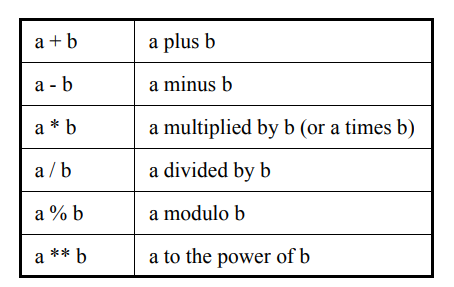
There are various kinds of arithmetic operators that can be useful: saturating, arbitrary size floating point, carry save, etc.

It is convenient to use the normal arithmetic operators for readability, rather than relying on function calls.

overload_declaration ::=

bind overload_operator function data_type function_identifier ( overload_proto_formals ) ;
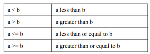
overload_operator ::= + | ++ | | – – | * | ** | / | % | == | != | < | <= | > | >= | =

overload_proto_formals ::= data_type {, data_type}

The overload declaration allows the arithmetic operators to be applied to data types that are normally illegal for them, such as unpacked structures. It does not change the meaning of the operators for those types where it is legal to apply them. This means that such code does not change behavior when operator overloading is used.

The overload declaration links an operator to a function prototype. The arguments are matched, and the type of the result is then checked. Multiple functions can have the same arguments and different return types. If no expected type exists because the operator is in a self-determined context, then a cast must be used to select the correct function. Similarly, if more than one expected type is possible, due to nested operators, and could match more than one function, a cast must be used to select the correct function. An expected result type exists in any of the following contexts:

  • The right-hand side of an assignment or assignment expression
  • Actual input argument of a task or function call
  • Input port connection of a module, interface, or program
  • Actual parameter to a module, interface, program, or class
  • Relational operator with unambiguous comparison
  • Inside a cast

For example, suppose there is a structure type float:

typedef struct {
bit sign;
bit [3:0] exponent;
bit [10:0] mantissa;
} float;

The + operator can be applied to this structure by invoking a function as indicated in the overloading declarations below:

bind + function float faddif(int, float);
bind + function float faddfi(float, int);
bind + function float faddrf(real, float);
bind + function float faddrf(shortreal, float);
bind + function float faddfr(float, real);
bind + function float faddfr(float, shortreal);
bind + function float faddff(float, float);
bind + function float fcopyf(float); // unary +
bind + function float fcopyi(int); // unary +
bind + function float fcopyr(real); // unary +
bind + function float fcopyr(shortreal); // unary +
float A, B, C, D;
assign A = B + C; //equivalent to A = faddff(B, C);
assign D = A + 1.0; //equivalent to A = faddfr(A, 1.0);

The overloading declaration links the + operator to each function prototype according to the equivalent argument types in the overloaded expression, which normally must match exactly. The exception is if the actual argument is an integral type and there is only one prototype with a corresponding integral argument, the actual is implicitly cast to the type in the prototype.

Note that the function prototype does not need to match the actual function declaration exactly. If it does not, then the normal implicit casting rules apply when calling the function. For example, the fcopyi function can be defined with an int argument:

function float fcopyi (int I);
float o;
o.sign = i[31];
o.exponent = 0;
o.mantissa = 0;

return o;
endfunction

Overloading the assignment operator also serves to overload implicit assignments or casting. Here these are using the same functions as the unary +.

bind = function float fcopyi(int); // cast int to float
bind = function float fcopyr(real); // cast real to float
bind = function float fcopyr(shortreal); // cast shortreal to float

The operators that can be overloaded are the arithmetic operators, the relational operators, and the assignment.

Note that the assignment operator from a float to a float cannot be overloaded here because it is already legal. Similarly, equality and inequality between floats cannot be overloaded. No format can be assumed for 0 or 1, so the user cannot rely on subtraction to give equality or on addition to give increments. Similarly, no format can be assumed for positive or negative, so comparison must be explicitly coded.

An assignment operator such as += is automatically built from both the + and = operators successively, where the = has its normal meaning. For example

float A, B;
bind + function float faddff(float, float);
always @(posedge clock) A += B; // equivalent to A = A + B

The scope and visibility of the overload declaration follow the same search rules as a data declaration. The overload declaration must be defined before use in a scope that is visible. The function bound by the overload declaration uses the same scope search rules as a function enabled from the scope where the operator is invoked.

<< Previous | Next >>

Tagged union expressions

A tagged union expression (packed or unpacked) is expressed using the keyword tagged followed by a tagged union member identifier, followed by an expression representing the corresponding member value. For void members, the member value expression is omitted. For Example:

typedef union tagged {
void Invalid;
int Valid;
} VInt;
VInt vi1, vi2;
vi1 = tagged Valid (23+34); // Create Valid int
vi2 = tagged Invalid; // Create an Invalid value

In the tagged union expressions below, the expressions in braces are structure expressions.

typedef union tagged {
struct {
bit [4:0] reg1, reg2, regd;
} Add;
union tagged {
bit [9:0] JmpU;
struct {
bit [1:0] cc;
bit [9:0] addr;
} JmpC;
} Jmp;
} Instr;
Instr i1, i2; // Create an Add instruction with its 3 register fields
i1 = ( e ? tagged Add { e1, 4, ed }; // struct members by position
: tagged Add { reg2:e2, regd:3, reg1:19 }); // by name (order irrelevant)
// Create a Jump instruction, with "unconditional" sub-opcode
i1 = tagged Jmp (tagged JmpU 239);
// Create a Jump instruction, with "conditional" sub-opcode
i2 = tagged Jmp (tagged JmpC { 2, 83 }); // inner struct by position
i2 = tagged Jmp (tagged JmpC { cc:2, addr:83 }); // by name

The type of a tagged union expression must be known from its context (e.g., it is used in the right-hand side of an assignment to a variable whose type is known, or it is has a cast, or it is used inside another expression from which its type is known). The expression evaluates to a tagged union value of that type. The tagged union expression can be completely type-checked statically: the only member names allowed after the tagged keyword are the member names for the expression type, and the member expression must have the corresponding member type.

An uninitialized variable of tagged union type shall be undefined. This includes the tag bits. A variable of tagged union type can be initialized with a tagged union expression provided the member value expression is a legal initializer for the member type.

Members of tagged unions can be read or assigned using the usual dot notation. Such accesses are completely type-checked, i.e., the value read or assigned must be consistent with the current tag. In general, this can require a runtime check. An attempt to read or assign a value whose type is inconsistent with the tag results in a runtime error.

All the following examples are legal only if the instruction variable instr currently has the tag Add:

x = i1.Add.reg1;
i1.Add = {19, 4, 3};
i1.Add.reg2 = 4;

<< Previous | Next >>