Introduction of Verilog Tasks and functions

Tasks and functions provide the ability to execute common procedures from several different places in a
description. They also provide a means of breaking up large procedures into smaller ones to make it easier to read and debug the source descriptions. This topic discusses the differences between tasks and functions, describes how to define and invoke tasks and functions, and presents examples of each.

Difference between tasks and functions:

The following rules distinguish tasks from functions:
— A function shall execute in one simulation time unit; a task can contain time-controlling statements.
— A function cannot enable a task; a task can enable other tasks and functions.
— A function shall have at least one input type argument and shall not have an output or inout type
argument; a task can have zero or more arguments of any type.
— A function shall return a single value; a task shall not return a value.

The purpose of a function is to respond to an input value by returning a single value. A task can support
multiple goals and can calculate multiple result values. However, only the output or inout type arguments
pass result values back from the invocation of a task. A function is used as an operand in an expression; the value of that operand is the value returned by the function.

We will discussing more details about functions & calling function in below link-
Verilog function & function calling

More Details about Task & calling task can be find in below link-
Verilog task & calling

<< Previous | Next >>

Verilog Tasks and task enabling

There are two alternate task declaration syntaxes.

a) The first syntax shall begin with the keyword task, followed by a name for the task and a semicolon, and ending with the keyword endtask. Task item declarations can specify the following:
— Input arguments
— Output arguments
— Inout arguments
— All data types that can be declared in a procedural block

Example 1—The following example illustrates the basic structure of a task definition with five arguments:
task my_task;
input a, b;
inout c;
output d, e;
begin
. . . // statements that perform the work of the task
. . .
c = foo1; // the assignments that initialize result regs
d = foo2;
e = foo3;
end
endtask

b) The second syntax shall begin with the keyword task, followed by a name for the task and a parenthesis-enclosed task_port_list. The task_port_list shall consist of zero or more comma separated task_port_items.

task my_task (input a, b, inout c, output d, e);
begin
. . . // statements that perform the work of the task
. . .
c = foo1; // the assignments that initialize result regs
d = foo2;
e = foo3;
end
endtask

Task memory usage and concurrent activation:
A task may be enabled more than once concurrently, variables declared in static tasks, including input, output, and inout type arguments, shall retain their values between invocations.
Variables declared in automatic tasks, including output type arguments, shall be initialized to the default
initialization value whenever execution enters their scope. input and inout type arguments shall be
initialized to the values passed from the expressions corresponding to these arguments listed in the taskenabling statements.

Disabling of named blocks and tasks:
The disable statement provides the ability to terminate the activity associated with concurrently active
procedures, while maintaining the structured nature of Verilog HDL procedural descriptions.
The disable statement can be used within blocks and tasks to disable the particular block or task containing the disable statement. The disable statement can be used to disable named blocks within a function, but cannot be used to disable functions.

Example 1—This example illustrates how a block disables itself.
begin : block_name
rega = regb;
disable block_name;
regc = rega; // this assignment will never execute
end

<< Previous | Next >>

Verilog Functions and function calling

A function definition shall begin with the keyword function, followed by the name of the function, followed either by a semicolon or by a function port list enclosed in parentheses and then a semicolon, and then shall end with the keyword endfunction.
Function inputs shall be declared one of two ways:
a) The first method shall have the name of the function followed by a semicolon. After the semicolon, one or more input declarations optionally mixed with block item declarations shall follow. After the function item declarations, there shall be a behavioral statement.

For example-

function [7:0] getbyte (input [15:0] address);
begin
       // code to extract low-order byte from addressed word
       . . .
getbyte = result_expression;
end
endfunction

b) The second method shall have the name of the function, followed by an open parenthesis and one or more input declarations, separated by commas. After all the input declarations, there shall be a close parenthesis and a semicolon. After the semicolon, there shall be zero or more block item declarations, followed by a behavioral statement.

For example-

function [7:0] getbyte (input [15:0] address);
begin
// code to extract low-order byte from addressed word
. . .
getbyte = result_expression;
end
endfunction

Function rules:

Functions are more limited than tasks. The following rules govern their usage:
a) A function definition shall not contain any time-controlled statements, that is, any statements containing #, @, or wait.
b) Functions shall not enable tasks.
c) A function definition shall contain at least one input argument.
d) A function definition shall not have any argument declared as output or inout.
e) A function shall not have any nonblocking assignments or procedural continuous assignments.
f) A function shall not have any event triggers.

<<add the example of function with EDA>>

<< Previous | Next >>

System tasks and functions

This describes system tasks and functions that are considered part of the Verilog-AMS HDL. It
also states whether a particular system task or function is supported in the digital context and if it is supported in the analog context. The system tasks and functions are divided into various categories.

1). Display system tasks:

The display group of system tasks is divided into three categories: the display and write tasks, strobed
monitoring tasks, and continuous monitoring tasks.

$strobe ( list_of_arguments ) ; — It provides the ability to display simulation data when the simulator has converged on a solution for all nodes.
$display ( list_of_arguments ) ; — It provides the same capabilities as $strobe
$monitor ( list_of_arguments ) ; — It provides the ability to monitor and display the values of any variables or expressions specified as arguments to the task.
$debug( list_of_arguments ) ; — It provides the capability to display simulation data while the analog simulator is solving the equations; it displays its arguments for each iteration of the analog solver.

Escape sequences for printing special characters: The escape sequences shown in below Table, when included in a string argument, print special characters.

Escape sequences for format specifications: The special character % indicates that the next character should be interpreted as a format specification that establishes the display format for a subsequent expression argument.

2) File input-output system tasks and functions:

The system tasks and functions for file-based operations are divided into the following categories:
— Functions and tasks that open and close files
— Tasks that output values into files
— Tasks that output values into variables
— Tasks and functions that read values from files and load into variables or memories

Opening and closing files: $fopen and $fclose

fd = $fopen ( ” file_name ” , type ) ;
$fclose ( fd ) ;

The function $fopen opens the file specified as the filename argument and returns either a 32-bit
multichannel descriptor or a 32-bit file descriptor determined by the absence or presence of the type
argument.
filename is a character string or is a reg containing a character string that names the file to be opened.

Types for file descriptors

3) Simulation control system tasks:

There are two simulation control system tasks:
a) $finish [ ( n ) ]
b) $stop [ ( n ) ]

The $finish system task simply makes the simulator exit and pass control back to the host operating system. If an expression is supplied to this task, then its value (0, 1, or 2) determines the diagnostic messages that are printed before the prompt is issued as shown in below Table. If no argument is supplied, then a value of 1 is taken as the default.

The $stop system task causes simulation to be suspended. This task takes an optional expression argument (0, 1, or 2) that determines what type of diagnostic message is printed. The amount of diagnostic messages output increases with the value of the optional argument passed to $stop.


<< Previous | Next >>

Verilog Structured procedures

All procedures in the Verilog HDL are specified within one of the following four statements:
— initial construct
— always construct
— Task
— Function
The initial and always constructs are enabled at the beginning of a simulation. The initial construct shall
execute only once, and its activity shall cease when the statement has finished. In contrast, the always
construct shall execute repeatedly. Its activity shall cease only when the simulation is terminated. There
shall be no implied order of execution between initial and always constructs. The initial constructs need not be scheduled and executed before the always constructs. There shall be no limit to the number of initial and always constructs that can be defined in a module.
Tasks and functions are procedures that are enabled from one or more places in other procedures. Tasks and functions are described in (<add link>).

Initial construct:

The following example illustrates use of the initial construct for initialization of variables at the start of
simulation-

initial begin
      areg = 0; // initialize a reg
      for (index = 0; index < size; index = index + 1)
          memory[index] = 0; //initialize memory word
end

Another typical usage of the initial construct is specification of waveform descriptions that execute once to provide stimulus to the main part of the circuit being simulated.

initial begin
      inputs = 'b000000; // initialize at time zero
      #10 inputs = 'b011001; // first pattern
      #10 inputs = 'b011011; // second pattern
      #10 inputs = 'b011000; // third pattern
      #10 inputs = 'b001000; // last pattern
end

Always construct:

The always construct, because of its looping nature, is only useful when used in conjunction with some form of timing control. If an always construct has no control for simulation time to advance, it will create a
simulation deadlock condition.
The following code, for example, creates a zero-delay infinite loop:
always areg = ~areg;
Providing a timing control to the above code creates a potentially useful description as shown in the
following:
always #half_period areg = ~areg;

<< Previous | Next >>

Verilog Block statements

The block statements are a means of grouping statements together so that they act syntactically like a single statement. There are two types of blocks in the Verilog HDL:
— Sequential block, also called begin-end block
— Parallel block, also called fork-join block
The sequential block shall be delimited by the keywords begin and end. The procedural statements in
sequential block shall be executed sequentially in the given order.
The parallel block shall be delimited by the keywords fork and join. The procedural statements in parallel
block shall be executed concurrently.

1). Sequential blocks:

A sequential block shall have the following characteristics:
— Statements shall be executed in sequence, one after another.
— Delay values for each statement shall be treated relative to the simulation time of the execution of
the previous statement.
— Control shall pass out of the block after the last statement executes.
For example: —A sequential block enables the following two assignments to have a deterministic result:

begin
areg = breg;
creg = areg; // creg stores the value of breg
end

The first assignment is performed, and areg is updated before control passes to the second assignment.

2). Parallel blocks:

A parallel block shall have the following characteristics:
— Statements shall execute concurrently.
— Delay values for each statement shall be considered relative to the simulation time of entering the
block.
— Delay control can be used to provide time-ordering for assignments.
— Control shall pass out of the block when the last time-ordered statement executes.

The following example codes show parallel –

fork
#50 r = 'h35;
#100 r = 'hE2;
#150 r = 'h00;
#200 r = 'hF7;
#250 -> end_wave;
join

3). Block names:

Both sequential and parallel blocks can be named by adding : name_of_block after the keywords begin
or fork. The naming of blocks serves several purposes:

— It allows local variables, parameters, and named events to be declared for the block.
— It allows the block to be referenced in statements such as the disable statement

<< Previous | Next >>

Procedural timing controls

The Verilog HDL has two types of explicit timing control over when procedural statements can occur. The
first type is a delay control, in which an expression specifies the time duration between initially encountering the statement and when the statement actually executes. The delay expression can be a
dynamic function of the state of the circuit, but it can be a simple number that separates statement executions in time. The delay control is an important feature when specifying stimulus waveform descriptions.

The second type of timing control is the event expression, which allows statement execution to be delayed until the occurrence of some simulation event occurring in a procedure executing concurrently with this procedure. A simulation event can be a change of value on a net or variable (an implicit event) or the occurrence of an explicitly named event that is triggered from other procedures (an explicit event). Most often, an event control is a positive or negative edge on a clock signal.
The procedural statements encountered so far all execute without advancing simulation time. Simulation
time can advance by one of the following three methods:

— A delay control, which is introduced by the symbol #
— An event control, which is introduced by the symbol @
— The wait statement, which operates like a combination of the event control and the while loop

1). Delay control:

A procedural statement following the delay control shall be delayed in its execution with respect to the
procedural statement preceding the delay control by the specified delay. If the delay expression evaluates to an unknown or high-impedance value, it shall be interpreted as zero delay. If the delay expression evaluates to a negative value, it shall be interpreted as a twos-complement unsigned integer of the same size as a time variable. Specify parameters are permitted in the delay expression. They can be overridden by SDF annotation, in which case the expression is reevaluated.

For example —The next three examples provide an expression following the number sign (#). Execution of the assignment is delayed by the amount of simulation time specified by the value of the expression.

#d rega = regb; // d is defined as a parameter
#((d+e)/2) rega = regb; // delay is average of d and e
#regr regr = regr + 1; // delay is the value in regr

2). Event control:

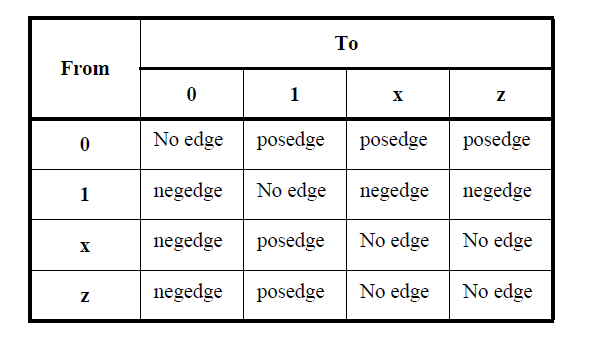
The execution of a procedural statement can be synchronized with a value change on a net or variable or the occurrence of a declared event. The value changes on nets and variable can be used as events to trigger the execution of a statement. This is known as detecting an implicit event. The event can also be based on the direction of the change, that is, toward the value 1 (posedge) or toward the value 0 (negedge).

— A negedge shall be detected on the transition from 1 to x, z, or 0, and from x or z to 0
— A posedge shall be detected on the transition from 0 to x, z, or 1, and from x or z to 1
Below table shows detecting posedge & negedge-

The following example shows illustrations of edge-controlled statements:

@r rega = regb; // controlled by any value change in the reg r
@(posedge clock) rega = regb; // controlled by posedge on clock
@(negedge clock) rega = regb; // controlled by negative edge

3). Named events:

A new data type, in addition to nets and variables, called event can be declared. An identifier declared as an event data type is called a named event. A named event can be triggered explicitly. It can be used in an event expression to control the execution of procedural statements in the same manner as event controls.

An event shall not hold any data. The following are the characteristics of a named event:
— It can be made to occur at any particular time.
— It has no time duration.
— Its occurrence can be recognized by using the event control

An event-controlled statement (for example, @trig rega = regb;) shall cause simulation of its
containing procedure to wait until some other procedure executes the appropriate event-triggering statement (for example, -> trig).

4). Level-sensitive event control:

The execution of a procedural statement can also be delayed until a condition becomes true. This is
accomplished using the wait statement, which is a special form of event control. The nature of the wait
statement is level-sensitive, as opposed to basic event control (specified by the @ character), which is edge sensitive.
The wait statement shall evaluate a condition; and, if it is false, the procedural statements following the wait statement shall remain blocked until that condition becomes true before continuing.
The following example shows the use of the wait statement to accomplish level-sensitive event control:

begin
     wait (!enable) #10 a = b;
     #10 c = d;
end

If the value of enable is 1 when the block is entered, the wait statement will delay the evaluation of the next statement (#10 a = b;) until the value of enable changes to 0. If enable is already 0 when the begin end block is entered, then the assignment “a = b;” is evaluated after a delay of 10 and no additional delay
occurs.

<< Previous | Next >>

Verilog Looping statements

There are four types of looping statements. These statements provide a means of controlling the execution of a statement zero, one, or more times.

forever Continuously executes a statement.
repeat Executes a statement a fixed number of times. If the expression evaluates to unknown or
high impedance, it shall be treated as zero, and no statement shall be executed.
while Executes a statement until an expression becomes false. If the expression starts out false,
the statement shall not be executed at all.
for Controls execution of its associated statement(s) by a three-step process, as follows:
a) Executes an assignment normally used to initialize a variable that controls the number
of loops executed.
b) Evaluates an expression. If the result is zero, the for loop shall exit. If it is not zero,
the for loop shall execute its associated statement(s) and then perform step c). If the
expression evaluates to an unknown or high-impedance value, it shall be treated as
zero.
c) Executes an assignment normally used to modify the value of the loop-control variable,
then repeats step b).

forever statement
| repeat ( expression ) statement
| while ( expression ) statement
| for ( variable_assignment ; expression ; variable_assignment ) statement

Example 1Repeat statement: In the following example of a repeat loop, add and shift operators implement a multiplier:

parameter size = 8, longsize = 16;
reg [size:1] opa, opb;
reg [longsize:1] result;
begin : mult
      reg [longsize:1] shift_opa, shift_opb;
      shift_opa = opa;
      shift_opb = opb;
      result = 0;
      repeat (size) begin
      if (shift_opb[1])
         result = result + shift_opa;
         shift_opa = shift_opa << 1; shift_opb = shift_opb >> 1;
      end
end

Example 2While statement: The following example counts the number of logic 1 values in rega:

begin : count1s
     reg [7:0] tempreg;
     count = 0;
     tempreg = rega;
     while (tempreg) begin
     if (tempreg[0])
        count = count + 1;
        tempreg = tempreg >> 1;
    end
end

<< Previous | Next >>

Verilog Case statement

The case statement is a multiway decision statement that tests whether an expression matches one of a
number of other expressions and branches accordingly. The case statement has the syntax shown in below-

case ( expression )
case_item { case_item } endcase
| casez ( expression )
case_item { case_item } endcase
| casex ( expression )
case_item { case_item } endcase

The case expression and the case item expression can be computed at run time; neither expression is
required to be a constant expression.
For Example 1:
The following example illustrates the use of a case statement to handle x and z values properly:

case (select[1:2])
2’b00: result = 0;
2’b01: result = flaga;
2’b0x,
2’b0z: result = flaga ? ‘bx : 0;
2’b10: result = flagb;
2’bx0,
2’bz0: result = flagb ? ‘bx : 0;
default result = ‘bx;
endcase

In above example, if select[1] is 0 and flaga is 0, then even if the value of select[2] is x or z, result should be 0—which is resolved by the third case.
The following example shows another way to use a case statement to detect x and z values.

case (sig)
1'bz: $display("signal is floating");
1'bx: $display("signal is unknown");
default: $display("signal is %b", sig);
endcase

Case statement with do-not-cares:

Two other types of case statements are provided to allow handling of do-not-care conditions in the case
comparisons. One of these treats high-impedance values (z) as do-not-cares, and the other treats both
high-impedance and unknown (x) values as do-not-cares.
These case statements can be used in the same way as the traditional case statement, but they begin with
keywords casez and casex, respectively.
Do-not-care values (z values for casez, z and x values for casex) in any bit of either the case expression or
the case items shall be treated as do-not-care conditions during the comparison, and that bit position shall not be considered. The do-not-care conditions in case expression can be used to control dynamically which bits should be compared at any time.

For Example —The following is an example of the casez statement. It demonstrates an instruction decode, where values of the most significant bits select which task should be called. If the most significant bit of reg_sel is a 1, then the task instruction1 is called, regardless of the values of the other bits of reg_sel.

reg [7:0] reg_sel;
casez (reg_sel)
    8'b1???????: instruction1(reg_sel);
    8'b01??????: instruction2(reg_sel);
    8'b00010???: instruction3(reg_sel);
    8'b000001??: instruction4(reg_sel);
endcase

<< Previous | Next >>

Verilog Conditional statement

The conditional statement (or if-else statement) is used to make a decision about whether a statement is
executed. Formally, the syntax is below

if ( expression ) statement_or_null
{ else if ( expression ) statement_or_null }
[ else statement_or_null ]

If the expression evaluates to true (that is, has a nonzero known value), the first statement shall be executed. If it evaluates to false (that is, has a zero value or the value is x or z), the first statement shall not execute. If there is an else statement and expression is false, the else statement shall be executed.

This sequence of if statements (known as an if-else-if construct) is the most general way of writing a
multiway decision. The expressions shall be evaluated in order. If any expression is true, the statement
associated with it shall be executed, and this shall terminate the whole chain. Each statement is either a
single statement or a block of statements.
The last else part of the if-else-if construct handles the none-of-the-above or default case where none of the other conditions were satisfied. Sometimes there is no explicit action for the default. In that case, the trailing else statement can be omitted, or it can be used for error checking to catch an impossible condition.

For example:
The following module fragment uses the if-else statement to test the variable index to decide whether one of three modify_segn regs has to be added to the memory address and which increment is to be added to the index reg. The first ten lines declare the regs and parameters.

// declare regs and parameters
reg [31:0] instruction, segment_area[255:0];
reg [7:0] index;
reg [5:0] modify_seg1,
modify_seg2,
modify_seg3;
parameter
segment1 = 0, inc_seg1 = 1,
segment2 = 20, inc_seg2 = 2,
segment3 = 64, inc_seg3 = 4,
data = 128;
// test the index variable
if (index < segment2) begin
instruction = segment_area [index + modify_seg1];
index = index + inc_seg1;
end
else if (index < segment3) begin
instruction = segment_area [index + modify_seg2];
index = index + inc_seg2;
end
else if (index < data) begin
instruction = segment_area [index + modify_seg3];
index = index + inc_seg3;
end
else
instruction = segment_area [index];

<< Previous | Next >>