Verilog Bitwise Operators

The bitwise operators shall perform bitwise manipulations on the operands; that is, the operator shall
combine a bit in one operand with its corresponding bit in the other operand to calculate 1 bit for the result.

Below are the results for each possible combinations

1 Bitwise binary AND operator:

2. Bitwise binary OR operator:

3. Bitwise binary exclusive or operator

<< Previous | Next >>

Verilog Logical Operators

The operators logical and (&&) and logical or (||) are logical connectives. The result of the evaluation of a logical comparison shall be 1 (defined as true), 0 (defined as false), or, if the result is ambiguous, the unknown value (x). The precedence of && is greater than that of ||, and both are lower than relational and equality operators. 

A third logical operator is the unary logical negation operator (!). The negation operator converts a nonzero or true operand into 0 and a zero or false operand into 1. An ambiguous truth value remains as x.

Example 1—If reg alpha holds the integer value 237 and beta holds the value zero, then the following
examples perform as described:
regA = alpha && beta; // regA is set to 0
regB = alpha || beta; // regB is set to 1

<< Previous | Next >>

Verilog Equality Operators

All four equality operators shall have the same precedence.

For the logical equality and logical inequality operators (== and !=), if, due to unknown or high-impedance bits in the operands, the relation is ambiguous, then the result shall be a 1-bit unknown value (x). 

For the case equality and case inequality operators (=== and !==), the comparison shall be done just as it is in the procedural case statement (see 9.5). Bits that are x or z shall be included in the comparison and shall match for the result to be considered equal. The result of these operators shall always be a known value, either 1 or 0.

<< Previous | Next >>

Verilog Rational Operators

Relational operators are used for comparing values. They return a Boolean result indicating the relationship between the operands.
Definitions of rational operator shown in below table-

An expression using these relational operators shall yield the scalar value 0 if the specified relation is false or the value 1 if it is true. If either operand of a relational operator contains an unknown (x) or highimpedance (z) value, then the result shall be a 1-bit unknown value (x).

When one or both operands of a relational expression are unsigned, the expression shall be interpreted as a comparison between unsigned values. If the operands are of unequal bit lengths, the smaller operand shall be zero-extended to the size of the larger operand. 

When both operands are signed, the expression shall be interpreted as a comparison between signed values. If the operands are of unequal bit lengths, the smaller operand shall be sign-extended to the size of the larger operand. 

If either operand is a real operand, then the other operand shall be converted to an equivalent real value and the expression shall be interpreted as a comparison between real values.

<< Previous | Next >>

Verilog Operators and Operands

We will understand the various Verilog operators and operands, their types, and their applications in digital circuit design.
Verilog operators are symbols that represent computations or operations on operands. They are classified into several categories based on their functionality.

Arithmetic operators:
Arithmetic operators perform mathematical operations on operands. Common arithmetic operators in Verilog such as addition, subtraction, multiplication, division, and modulus.

reg [3:0] result;
reg [3:0] a = 3;
reg [3:0] b = 5;
always @* begin
    result = a + b;   // Addition
    result = a - b;   // Subtraction
    result = a * b;   // Multiplication
    result = a / b;   // Division
    result = a % b;   // Modulus
end

<< Previous | Next >>

Parameters

Parameters do not belong to either the variable or the net group. Parameters are not variables; they are constants. There are two types of parameters: module parameters and specify parameters. It is illegal to redeclare a name already declared by a net, parameter, or variable declaration. 

Both types of parameters accept a range specification. By default, parameters and specify params shall be as wide as necessary to contain the value of the constant, except when a range specification is present.

For example: 
parameter msb = 7; // defines msb as a constant value 7 
parameter e = 25, f = 9; // defines two constant numbers 
parameter r = 5.7; // declares r as a real parameter 
parameter byte_size = 8, byte_mask = byte_size - 1; 
parameter average_delay = (r + f) / 2; 
parameter signed [3:0] mux_selector = 0;

Parameters represent constants; hence, it is illegal to modify their value at run time. However, module parameters can be modified at compilation time to have values that are different from those specified in the declaration assignment. This allows customization of module instances. A parameter can be modified with the defparam statement or in the module instance statement. Typical uses of parameters are to specify delays and width of variables.

local parameters are identical to parameters except that they cannot directly be modified by defparam statements.

<< Previous | Next >>

Memory

A one-dimensional array with elements of type reg is also called a memory. These memories can be used to model read-only memories (ROMs), random access memories (RAMs), and reg files. Each reg in the array is known as an element or word and is addressed by a single array index.

Array declarations examples:

Array declarations examples:
reg [7:0] mema[0:255]; // declares a memory mema of 256 8-bit // registers. The indices are 0 to 255 
integer inta[1:64]; // an array of 64 integer values

Assignment to above array elements-
mema = 0; // Illegal syntax- Attempt to write to entire array 
arrayb[1] = 0; // Illegal Syntax - Attempt to write to elements // [1][0]..[1][255] 
arrayb[1][12:31] = 0; // Illegal Syntax - Attempt to write to // elements [1][12]..[1][31] 
mema[1] = 0; // Assigns 0 to the second element of mema 
arrayb[1][0] = 0; // Assigns 0 to the bit referenced by indices // [1][0] 
inta[4] = 33559; // Assign decimal number to integer in array 
chng_hist[t_index] = $time; // Assign current simulation time to element addressed by integer index

<< Previous | Next >>

Verilog Data Types

Mainly Data types are used to represent the data storage and transmission elements in digital hardware.
Lets understand all fundamentals about Data types-
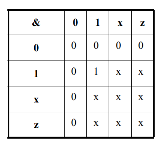
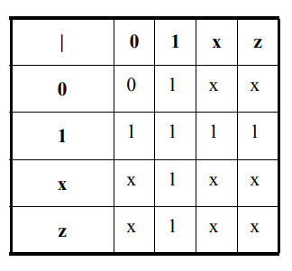
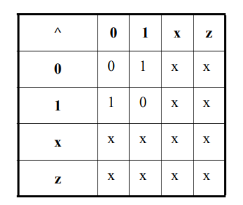
Value set:
It have four basic values-

0 – represents a logic zero, or a false condition 
1 – represents a logic one, or a true condition 
x – represents an unknown logic value 
z – represents a high-impedance state 
Here – X i.e unknown value might be either 0 or 1.

Nets and variables: 
There are two main groups of data types: the variable data types and the net data types. These two groups differ in the way that they are assigned and hold values. 

Net types: Net can represent physical connections between structural entities, such as gates. A net shall not store a value (except for the trireg net). 
If no driver is connected to a net, its value shall be high-impedance (z) unless the net is a trireg, in which case it shall hold the previously driven value.

There are several distinct types of nets-
Wire and tri nets:
The wire and tri nets connect elements. The net types wire and tri shall be identical in their syntax and functions; two names are provided so that the name of a net can indicate the purpose of the net in that model. A wire net can be used for nets that are driven by a single gate or continuous assignment. The tri net type can be used where multiple drivers drive a net.

A variable: shall store a value from one assignment to the next. The default initialization value for reg, time, and integer data types shall be the unknown value, x.

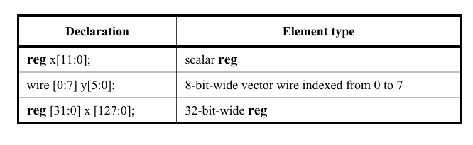
Vectors: A net or reg declaration without a range specification shall be considered 1 bit wide and is known as a scalar. Multibit net and reg data types shall be declared by specifying a range, which is known as a vector.
Vector nets and regs shall obey laws of arithmetic modulo-2 to the power n (2n), where n is the number of bits in the vector. Vector nets and regs shall be treated as unsigned quantities, unless the net or reg is
declared to be signed or is connected to a port that is declared to be signed.

For example:
wand w;    // a scalar net of type "wand"
tri [15:0] busa;   // a three-state 16-bit bus
trireg (small) storeit;  // a charge storage node of strength small
reg a;  //scalar reg
reg[3:0] v;   // a 4-bit vector reg made up of (from most to least significant)v[3], v[2], v[1], and v[0]
reg signed [3:0] signed_reg;   // a 4-bit vector in range -8 to 7
reg [-1:4] b;  // a 6-bit vector reg
wire w1, w2;  // declares two wires
reg [4:0] x, y, z;  // declares three 5-bit regs

Regs:
Assignments to a reg are made by procedural assignments. Because the reg holds a value between assignments, it can be used to model hardware registers. Edge-sensitive (i.e., flip-flops) and level sensitive (i.e., reset-set and transparent latches) storage elements can be modeled.

For example: 
reg a; // a scalar reg 
reg[1:0] v; // a 2-bit vector reg made up of v[1], and v[0] 
wire w1, w2; // declares two wires 

Integers, reals, times, and realtimes:
An integer is a general-purpose variable used for manipulating quantities that are not regarded as hardware registers.
A time variable is used for storing and manipulating simulation time quantities in situations where timing checks are required and for diagnostics and debugging purposes. This data type is typically used in conjunction with the $time system function. 

For example: 
integer a; // integer value 
time last_chng; // time value 
real float ; // a variable to store a real value 
realtime rtime ; // a variable to store time as a real value

Arrays:
Arrays can be used to group elements of the declared element type into multidimensional objects. Arrays shall be declared by specifying the element address range(s) after the declared identifier.

Memory:
A one-dimensional array with elements of type reg is also called a memory. These memories can be used to model read-only memories (ROMs), random access memories (RAMs), and reg files. Each reg in the array is known as an element or word and is addressed by a single array index.

Array declarations examples:

reg [7:0] mema[0:255]; // declares a memory mema of 256 8-bit // registers. The indices are 0 to 255 
integer inta[1:64]; // an array of 64 integer values

Assignment to above array elements-

mema = 0; // Illegal syntax- Attempt to write to entire array 
arrayb[1] = 0; // Illegal Syntax - Attempt to write to elements // [1][0]..[1][255] 
arrayb[1][12:31] = 0; // Illegal Syntax - Attempt to write to // elements [1][12]..[1][31] 
mema[1] = 0; // Assigns 0 to the second element of mema 
arrayb[1][0] = 0; // Assigns 0 to the bit referenced by indices // [1][0] 
inta[4] = 33559; // Assign decimal number to integer in array 
chng_hist[t_index] = $time; // Assign current simulation time to element addressed by integer index

Parameters:
Parameters do not belong to either the variable or the net group. Parameters are not variables; they are constants. There are two types of parameters: module parameters and specify parameters. It is illegal to redeclare a name already declared by a net, parameter, or variable declaration. 

Both types of parameters accept a range specification. By default, parameters and specify params shall be as wide as necessary to contain the value of the constant, except when a range specification is present.

For example: 
parameter msb = 7; // defines msb as a constant value 7 
parameter e = 25, f = 9; // defines two constant numbers 
parameter r = 5.7; // declares r as a real parameter 
parameter byte_size = 8, byte_mask = byte_size - 1; 
parameter average_delay = (r + f) / 2; 
parameter signed [3:0] mux_selector = 0;

Parameters represent constants; hence, it is illegal to modify their value at run time. However, module parameters can be modified at compilation time to have values that are different from those specified in the declaration assignment. This allows customization of module instances. A parameter can be modified with the defparam statement or in the module instance statement. Typical uses of parameters are to specify delays and width of variables.

<< Previous | Next >>

Verilog Introduction

Verilog is a language using which a designer can specify the behavior, or the functionality, or the structure of some given hardware; some specified hardware circuit. this language is also called Hardware Description Languages (HDL).
HDL’s allows the design to be simulated earlier in the design cycle in order to correct errors or experiment with different architectures. Designs described in HDL are technology-independent, easy to design and debug, and are usually more readable than schematics, particularly for large circuits.

Verilog can be used at several levels-

1) High level Behavioral

  • Behavioral models in Verilog contain procedural statements, which control the simulation and manipulate variables of the data types, these all statements are contained within the procedures. Each of the procedure has an activity flow associated with it.
  • Below is a Half Adder example-

//below is code for half adder            
module half_adder(a,b,sum,cout);
input a,b;
output sum,cout; // sum and carry

assign sum = a^b;
assign cout = a&b ;
endmodule

2) Register transfer level

  • Designs using the Register-Transfer Level specify a circuit’s characteristics using operations and the transfer of data between the registers

3) Gate level
Designing circuits using basic logic gates is known as gate-level modeling.
It is a low-level abstraction that describes design in terms of gates.

Below is simple gate level design of a Half Adder

// code your half adder design             
module half_add(a,b,s,c); 
  input a,b;
  output s,c;
 
// gate level design of half adder  
  xor x1(s,a,b);
  and a1(c,a,b);
endmodule :half_add