Verilog nonblocking procedural assignment

The nonblocking procedural assignment allows assignment scheduling without blocking the procedural
flow. The nonblocking procedural assignment statement can be used whenever several variable assignments within the same time step can be made without regard to order or dependence upon each other.

The nonblocking assignment operator is the same operator as the less-than-or-equal-to relational operator. The interpretation shall be decided from the context in which <= appears. When <= is used in an expression, it shall be interpreted as a relational operator; and when it is used in a nonblocking procedural assignment, it shall be interpreted as an assignment operator.

The nonblocking procedural assignments shall be evaluated in two steps as discussed in Scheduling semantics(<add link>). These
two steps are shown in the following example:

Example 1:
module evaluates2 (out);
output out;
reg a, b, c;
initial begin
    a = 0;
    b = 1;
    c = 0;
end
always c = #5 ~c;
always @(posedge c) begin
    a <= b; // evaluates, schedules,
    b <= a; // and executes in two steps
end
endmodule

Below are steps to execute above example:
1) .At posedge c, the simulator evaluates the right-hand sides of the nonblocking assignments and schedules the assignments of the new values at the end of the nonblocking assign update events.
2). When the simulator activates the nonblocking assign update events, the simulator updates the left-hand side of each nonblocking assignment statement.

Example 2
//non_block1.v
module non_block1;
reg a, b, c, d, e, f;
//blocking assignments
initial begin
    a = #10 1; // a will be assigned 1 at time 10
    b = #2 0; // b will be assigned 0 at time 12
    c = #4 1; // c will be assigned 1 at time 16
end
//non-blocking assignments
initial begin
    d <= #10 1; // d will be assigned 1 at time 10
    e <= #2 0; // e will be assigned 0 at time 2
    f <= #4 1; // f will be assigned 1 at time 4
end
endmodule

<< Previous | Next >>

Verilog Blocking procedural assignments

A blocking procedural assignment statement shall be executed before the execution of the statements that follow it in a sequential block (<add link>). A blocking procedural assignment statement shall not prevent the execution of statements that follow it in a parallel block(<add link>).
The = assignment operator used by blocking procedural assignments is also used by procedural continuous assignments and continuous assignments.

For example:
The following examples show blocking procedural assignments:

rega = 0;
rega[3] = 1; // a bit-select
rega[3:5] = 7; // a part-select
mema[address] = 8'hff; // assignment to a mem element
{carry, acc} = rega + regb; // a concatenation

<< Previous | Next >>

Verilog Procedural continuous assignments

The procedural continuous assignments (using keywords assign and force) are procedural statements that allow expressions to be driven continuously onto variables or nets.
The left-hand side of the assignment in the assign statement shall be a variable reference or a concatenation of variables. It shall not be a memory word (array reference) or a bit-select or a part-select of a variable.
In contrast, the left-hand side of the assignment in the force statement can be a variable reference or a net reference. It can be a concatenation of any of the above. Bit-selects and part-selects of vector variables are not allowed.

The assign and deassign procedural statements:

The assign procedural continuous assignment statement shall override all procedural assignments to a
variable. The deassign procedural statement shall end a procedural continuous assignment to a variable. The value of the variable shall remain the same until the variable is assigned a new value through a procedural assignment or a procedural continuous assignment. The assign and deassign procedural statements allow, for example, modeling of asynchronous clear/preset on a D-type edge-triggered flip-flop, where the clock is inhibited when the clear or preset is active.
If the keyword assign is applied to a variable for which there is already a procedural continuous assignment, then this new procedural continuous assignment shall deassign the variable before making the new procedural continuous assignment.

For example:
The following example shows a use of the assign and deassign procedural statements in a behavioral
description of a D-type flip-flop with preset and clear inputs:

module dff (q, d, clear, preset, clock);
output q;
input d, clear, preset, clock;
reg q;
always @(clear or preset)
    if (!clear)
        assign q = 0;
    else if (!preset)
        assign q = 1;
    else
        deassign q;
always @(posedge clock)
    q = d;
endmodule

If either clear or preset is low, then the output q will be held continuously to the appropriate constant
value, and a positive edge on the clock will not affect q. When both the clear and preset are high, then
q is deassigned.

The force and release procedural statements:

Another form of procedural continuous assignment is provided by the force and release procedural
statements. These statements have a similar effect to the assign-deassign pair, but a force can be applied to nets as well as to variables. The left-hand side of the assignment can be a variable, a net, a constant bit-select of a vector net, a part-select of a vector net, or a concatenation. It cannot be a memory word (array reference) or a bit-select or a part-select of a vector variable.

A force procedural statement on a net shall override all drivers of the net—gate outputs, module outputs, and continuous assignments—until a release procedural statement is executed on the net. When released, the net shall immediately be assigned the value determined by the drivers of the net.

For example:

module test;
reg a, b, c, d;
wire e;
and and1 (e, a, b, c);
initial begin
    $monitor("%d d=%b,e=%b", $stime, d, e);
    assign d = a & b & c;
    a = 1;
    b = 0;
    c = 1;
   #10;
   force d = (a | b | c);
   force e = (a | b | c);
   #10;
   release d;
   release e;
   #10 $finish;
end
endmodule

In this example, an and gate instance and1 is “patched” to act like an or gate by a force procedural
statement that forces its output to the value of its ORed inputs, and an assign procedural statement of
ANDed values is “patched” to act like an assign statement of ORed values.
The right-hand side of a procedural continuous assignment or a force statement can be an expression. This shall be treated just as a continuous assignment; that is, if any variable on the right-hand side of the
assignment changes, the assignment shall be reevaluated while the assign or force is in effect.

<< Previous | Next >>

Verilog Behavioral modeling

Verilog behavioral models contain procedural statements that control the simulation and manipulate
variables of the data types previously described. These statements are contained within procedures. Each
procedure has an activity flow associated with it.
The activity starts at the control constructs initial and always. Each initial construct and each always
construct starts a separate activity flow. All of the activity flows are concurrent to model the inherent
concurrence of hardware.

The following example shows a complete Verilog behavioral model-

module behave;
reg [1:0] a, b;
initial begin
    a = 'b1;
    b = 'b0;
end
always begin
    #50 a = ~a;
end
always begin
    #100 b = ~b;
end
endmodule

During simulation of this model, all of the flows defined by the initial and always constructs start together at simulation time zero. The initial constructs execute once, and the always constructs execute repetitively.
In this model, the reg variables a and b initialize to 1 and 0, respectively, at simulation time zero. The initial construct is then complete and does not execute again during this simulation run. This initial construct contains a begin-end block (also called a sequential block) of statements. In this begin-end block, a is initialized first, followed by b.
The always constructs also start at time zero, but the values of the variables do not change until the times
specified by the delay controls (introduced by #) have elapsed. Thus, reg a inverts after 50 time units and
reg b inverts after 100 time units. Because the always constructs repeat, this model will produce two square waves. The reg a toggles with a period of 100 time units, and reg b toggles with a period of 200 time units.
The two always constructs proceed concurrently throughout the entire simulation run.

Procedural assignments:
Procedural assignments are used for updating reg, integer, time, real, realtime,
and memory data types. There is a significant difference between procedural assignments and continuous assignments:

Continuous assignments drive nets and are evaluated and updated whenever an input operand
changes value.
Procedural assignments update the value of variables under the control of the procedural flow
constructs that surround them.

The right-hand side of a procedural assignment can be any expression that evaluates to a value. The lefthand side shall be a variable that receives the assignment from the right-hand side. The left-hand side of a procedural assignment can take one of the following forms:
— reg, integer, real, realtime, or time data type: an assignment to the name reference of one of these
data types.
— Bit-select of a reg, integer, or time data type: an assignment to a single bit that leaves the other bits
untouched.
— Part-select of a reg, integer, or time data type: a part-select of one or more contiguous bits that
leaves the rest of the bits untouched.
— Memory word: a single word of a memory.
— Concatenation or nested concatenation of any of the above: a concatenation or nested concatenation
of any of the previous four forms. Such specification effectively partitions the result of the righthand
expression and assigns the partition parts, in order, to the various parts of the concatenation or
nested concatenation.

The Verilog HDL contains two types of procedural assignment statements:
Blocking procedural assignment statements
Nonblocking procedural assignment statements
Blocking and nonblocking procedural assignment statements specify different procedural flows in
sequential blocks.

<< Previous | Next >>

Verilog Procedural assignments

The primary discussion of procedural assignments is in Procedural assignments<add link>. However, a description of the basic ideas in this clause highlights the differences between continuous assignments and procedural assignments.

As stated in Continuous assignments<add link>, continuous assignments drive nets in a manner similar to the way gates drive nets. The
expression on the right-hand side can be thought of as a combinatorial circuit that drives the net
continuously. In contrast, procedural assignments put values in variables. The assignment does not have
duration; instead, the variable holds the value of the assignment until the next procedural assignment to that variable.

Procedural assignments occur within procedures such as always, initial (see Structured procedures <add link>), task, and function(see Tasks and functions <add link>) and can be thought of as “triggered” assignments. The trigger occurs when the flow of execution in the simulation reaches an assignment within a procedure. Reaching the assignment can be controlled by conditional statements. Event controls, delay controls, if statements, case statements, and looping statements can all be used to control whether assignments are evaluated. topic Behavioral modeling <add link> gives details and examples.

Variable declaration assignment:
The variable declaration assignment is a special case of procedural assignment as it assigns a value to a
variable. It allows an initial value to be placed in a variable in the same statement that declares the variable.
The assignment shall be to a constant expression. The assignment does not have duration; instead, the
variable holds the value until the next assignment to that variable. Variable declaration assignments to an
array are not allowed. Variable declaration assignments are only allowed at the module level. If the same
variable is assigned different values both in an initial block and in a variable declaration assignment, the
order of the evaluation is undefined.

 Example 1—Declare two real variables, assigned to the values 2.5 and 300,000.
 real r1 = 2.5, n300k = 3E6;

 Example 2—Declare a time variable and realtime variable with initial values.
 time t1 = 25;
 realtime rt1 = 2.5;

<< Previous | Next >>

Verilog Continuous assignments

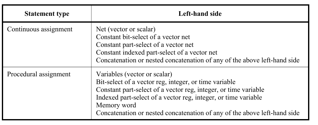
Continuous assignments shall drive values onto nets, both vector and scalar. This assignment shall occur
whenever the value of the right-hand side changes. Continuous assignments provide a way to model
combinational logic without specifying an interconnection of gates. Instead, the model specifies the logical expression that drives the net.

The net declaration assignment:.
The first two alternatives in the net declaration are discussed in Nets and variables(<add link>). The third alternative, the net declaration assignment, allows a continuous assignment to be placed on a net in the same statement that declares the net.
For example:
The following is an example of the net declaration form of a continuous assignment:

wire (strong1, pull0) mynet = enable ;

The continuous assignment statement:
The continuous assignment statement shall place a continuous assignment on a net data type. The net may be explicitly declared or may inherit an implicit declaration in accordance with the implicit declaration rules defined in Implicit declarations Assignments on nets shall be continuous and automatic. In other words, whenever an operand in the right hand expression changes value, the whole right-hand side shall be evaluated. If the new value is different from the previous value, then the new value shall be assigned to the left-hand side.

For example:
The following example describes a module with one 16-bit output bus. It selects between one of
four input busses and connects the selected bus to the output bus.

module select_bus(busout, bus0, bus1, bus2, bus3, enable, s);
 parameter n = 16;
 parameter Zee = 16'bz;
 output [1:n] busout;
 input [1:n] bus0, bus1, bus2, bus3;
 input enable;
 input [1:2] s;
 tri [1:n] data;
 // net declaration
 // net declaration with continuous assignment
 tri [1:n] busout = enable ? data : Zee;
 // assignment statement with four continuous assignments
 assign
 data = (s == 0) ? bus0 : Zee,
 data = (s == 1) ? bus1 : Zee,
 data = (s == 2) ? bus2 : Zee,
 data = (s == 3) ? bus3 : Zee;
 endmodule

The following sequence of events is experienced during simulation of this example:
a) The value of s, a bus selector input variable, is checked in the assign statement. Based on the value
of s, the net data receives the data from one of the four input buses.
b) The setting of data net triggers the continuous assignment in the net declaration for busout. If
enable is set, the contents of data are assigned to busout; if enable is 0, the contents of Zee are
assigned to busout.

Delays:
A delay given to a continuous assignment shall specify the time duration between a right-hand operand
value change and the assignment made to the left-hand side. If the left-hand references a scalar net, then the delay shall be treated in the same way as for gate delays; that is, different delays can be given for the output rising, falling, and changing to high impedance (see Gate- and switch-level modeling <add link>).

If the left-hand references a vector net, then up to three delays can be applied. The following rules determine
which delay controls the assignment:
— If the right-hand side makes a transition from nonzero to zero, then the falling delay shall be used.
— If the right-hand side makes a transition to z, then the turn-off delay shall be used.
— For all other cases, the rising delay shall be used.
Specifying the delay in a continuous assignment that is part of the net declaration shall be treated differently
from specifying a net delay and then making a continuous assignment to the net. A delay value can be
applied to a net in a net declaration, as in the following example:

wire #10 wireA;

This syntax, called a net delay, means that any value change that is to be applied to wireA by some other
statement shall be delayed for ten time units before it takes effect. When there is a continuous assignment in a declaration, the delay is part of the continuous assignment and is not a net delay. Thus, it shall not be added to the delay of other drivers on the net.

Strength:

The driving strength of a continuous assignment can be specified by the user.
A drive strength specification shall contain one strength value that applies when the value being assigned to the net is 1 and a second strength value that applies when the assigned value is 0.

The following keywords shall specify the strength value for an assignment of 1:
supply1 strong1 pull1 weak1 highz1
The following keywords shall specify the strength value for an assignment of 0:
supply0 strong0pull0 weak0 highz0

<< Previous | Next >>

Verilog Assignments Introduction

The assignment is the basic mechanism for placing values into nets and variables. There are two basic forms of assignments:
— The continuous assignment, which assigns values to nets
— The procedural assignment, which assigns values to variables
There are two additional forms of assignments, assign/de-assign and force/release, which are called procedural continuous assignments.

An assignment consists of two parts, a left-hand side and a right-hand side, separated by the equals ( = )
character; or, in the case of nonblocking procedural assignment, the less-than-equals ( <= ) character pair.

The right-hand side can be any expression that evaluates to a value. The left-hand side indicates the variable to which the right-hand side value is to be assigned. The left-hand side can take one of the forms given in below Table, depending on whether the assignment is a continuous assignment or a procedural assignment.

<< Previous | Next >>

Verilog Conditional Operator

The evaluation of a conditional operator shall begin with a logical equality comparison of expression1 with zero, termed the condition. If the condition evaluates to false (0), then expression3 shall be
evaluated and used as the result of the conditional expression. If the condition evaluates to true (1), then
expression2 is evaluated and used as the result.

result = expression1(condition) ? expression2 : expression3

For example:
The following example of a three-state output bus illustrates a common use of the conditional operator:
The bus called data is driven onto busa when drive_busa is 1. If drive_busa is 0, then an
value 8 is driven onto busa. Otherwise, busa is not driven.

wire [15:0] busa = drive_busa ? data : 16'b8;

<< Previous | Next >>

Verilog Shift Operators

There are two types of shift operators: the logical shift operators, << and >>, and the arithmetic shift operators, <<< and >>>. The left shift operators, << and <<<, shall shift their left operand to the left by the number by the number of bit positions given by the right operand. In both cases, the vacated bit positions shall be filled with zeroes. The right shift operators, >> and >>>, shall shift their left operand to the right by the number of bit positions given by the right operand. The logical right shift shall fill the vacated bit positions with zeroes.

For example —In this example, the reg result is assigned the binary value 0100, which is 0001 shifted to the left two positions and zero-filled.

module shift; 
reg [3:0] start, result; 
initial begin start = 1; 
result = (start << 2); 
end
endmodule

<< Previous | Next >>

Verilog Reduction Operators

The unary reduction operators shall perform a bitwise operation on a single operand to produce a single-bit result. For reduction and, reduction or, and reduction xor operators, the first step of the operation shall apply the operator between the first bit of the operand and the second using below logic Tables.
The second and subsequent steps shall apply the operator between the 1-bit result of the prior step and the next bit of the operand using the same logic table.
Reduction unary and operator:

Reduction unary or operator:

Reduction unary exclusive or operator:

For example: below table shows the results of applying reduction operators on different operands-

<< Previous | Next >>